Vintage MiniKorg 700 Repairs

I acquired a broken MiniKorg (Univox badge, mode 700 single oscillator) as part of a deal selling a working Minikorg. The seller’s tech says it is not repairable. I don’t believe that. This is a lengthy process (for me!) so here is part one of the repair video. Part Two is in progress as I am troubleshooting as I write this.

I opened it up and found the main oscillator was missing. This was no surprise since I was told it was bad. I had already bought a new one from https://enlo-1.com/ and installation was easy. They also sell filter replacements. Some other wiring was broken, probably because it was shipped to me with the oscillator circuit not mounted NOT MOUNTED. Yes, circuit boards flopping around breaks wires. I fixed the wires and tested the system.

I could trigger notes, the filter and related controls work. Repeat works. Nothing related to pitch, other than changing the footage, worked. I only could play a single note- guessing the high C on the keyboard. I tested the voltage output from the keyboard for key presses and it produces increasing voltage as you moved up the keyboard, as it should.

I know the divider (MN133) is mostly working, since I hear octave changes from 2′ to 4′ to 8′ to 16′. I don’t hear a change from 16′ to 32′ this could be the switch or it could be the divider. Easy to check, since the divider produces outputs all the time. Just hook up a scope and read the output waveform and see if I have different ones where I should.

Hz/Volt

So how does the Korg Hz/Volt system work? The voltage range was about 11.5 volts. I don’t know the base frequency range of the VCO (what three octave range it plays in). The VCO frequency is proportional to the control voltage coming in. The voltage out of the keyboard doubles for each octave. In a Moog Volt/Octave system each octave change is just one volt.

Troubleshooting

This board is full of dangers; namely, several locations where AC is present up to line voltage (123VAC in my house)! The case is metal and it is the ground for the system. Touch either fuse holder lead, either power switch lead, or where the brown wire connects to the little bus by the transformer and you will be electrocuted (yes, injury or death can result) if you are touching the case or grounded some other way. Great case for the “one hand rule” which is keep one hand in your pocket while taking measurements while the synth is energized.

Some foolishly believe low-voltage household circuits can’t kill you. They can and do every year in the US. You can search for yourself, but here is a good report. https://www.cpsc.gov/s3fs-public/Electrocution-Report-2004-to-2013.pd

Extra risks for circuit board damage exist, too. Each board is mounted to the metal case, which is ground. If you power it on without the boards screwed down, all the leads along the edge of the board (under the wire bundle) run the risk of contact to ground, causing numerous short circuits.

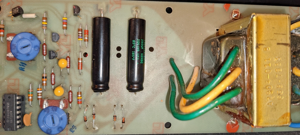
This is why you ALWAYS open up and inspect a "for parts" or otherwise broken synth that came in the mail before powering it on. You can do much more damage than there already is.

When screwed down, there is a gap between the solder joints and the case. Non-conductive standoffs would have been a better choice. I know of this problem because I did it and overheated an electrolytic cap (now replaced) until the magic smoke came out. If you do have to take reading on the bottom of a board, support it perpendicular to the case and clamped in place so it cannot fall on the ground case.

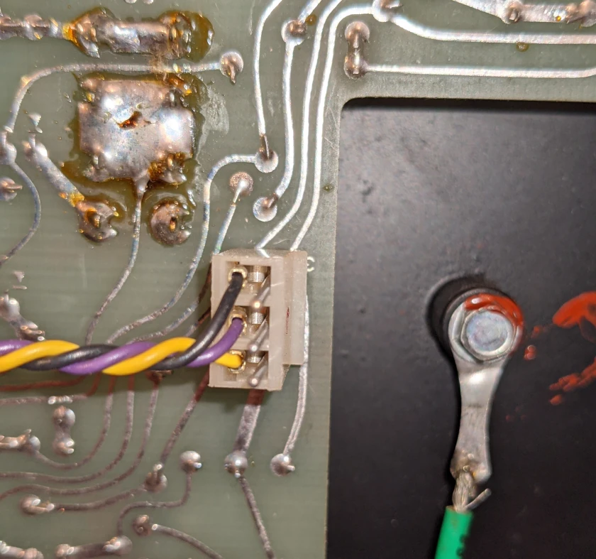
The fuse holder and power switch now have heat-shrink on the bare contacts. The best I can do for the transformer bus is glue on some cardboard.

NOW ON TO TROUBLESHOOTING…

I need to test the control voltage input to the VCO and see if it is changing or not. The VCO is fed a signal derived from the keyboard voltage output, and this controls the frequency that the oscillator outputs. The output range covers 3 octaves. Exactly which 3 is controlled by the footage selection.

I also need to check the VCO output. I believe it is pin 7. If the input CV signal is changing, I should see a changing output. I do not hear any changes, though, which is why I think the problem is upstream of the VCO. I hope that is the case and that I do not have divider problems (MN131) since those chips are hard to come by.

Oscillator Circuit Board

There is quite a lot of circuitry involved, and many inputs that affect the operation of the VCO. The Vibrato signal is an input to the VCO and affects the output. Portamento, Bender, and pitch control (tuning) also have inputs to the VCO. None are having any effect right now.

This block diagram of the synth is useful for troubleshooting and overall understanding.

I need to check the MN131A (or MN133- same function) divider outputs (pins 2, 3, 10, 11 are used). The input used is pin 9.

There are numerous numbered points on the circuit board. I can test wave shaping outputs, for example. I am optimistic further testing will narrow down the region of the circuit board causing the trouble.

Early Results

The 741 IC is working, though honestly appears to do nothing. The output voltage (pin 6) changes as you go up the keyboard, but is about the same voltage as the input. It is not exactly the same due to a 22KOhm feedback resistor. So what is this unity gain op amp for? Current control.

https://www.learningaboutelectronics.com/Articles/Unity-gain-buffer

In case you are wondering what pin is what in a TO-5 package, here you go. Pin 8 has the tab sticking out.

IC741 TO-5 pinout

The CV input at pin 1 of the VCO also changes like it should. It comes from the 741. My VCO is brand new, so I think it is OK but will test with the o-scope.

The VCO output (pin 7) is a nice saw tooth of about 7v peak to peak.

I checked the frequency divider outputs (pins 2, 3, 10, 11) and I see properly divided signals! So where is the sound going??

Points 34/35 show the vibrato wave form and the speed and depth controllers alter it as they should. I also see pitch changes (for tuning) at point 31. Waveforms are at the following numbered points:

  • 48 (saw)
  • 49 (square)
  • 50 (square with a little chorus or PWM- you can see the jitter on an o-scope)
  • 55 (triangle)

When playing the keyboard all of these points output the sound perfectly. You can tap into the audio signal with a probe and give it a listen. Vibrato, Bender, Pitch and Portamento work. The signal is pre-filter, though, so no filter (or related effects like Bright or Expand) or volume control.

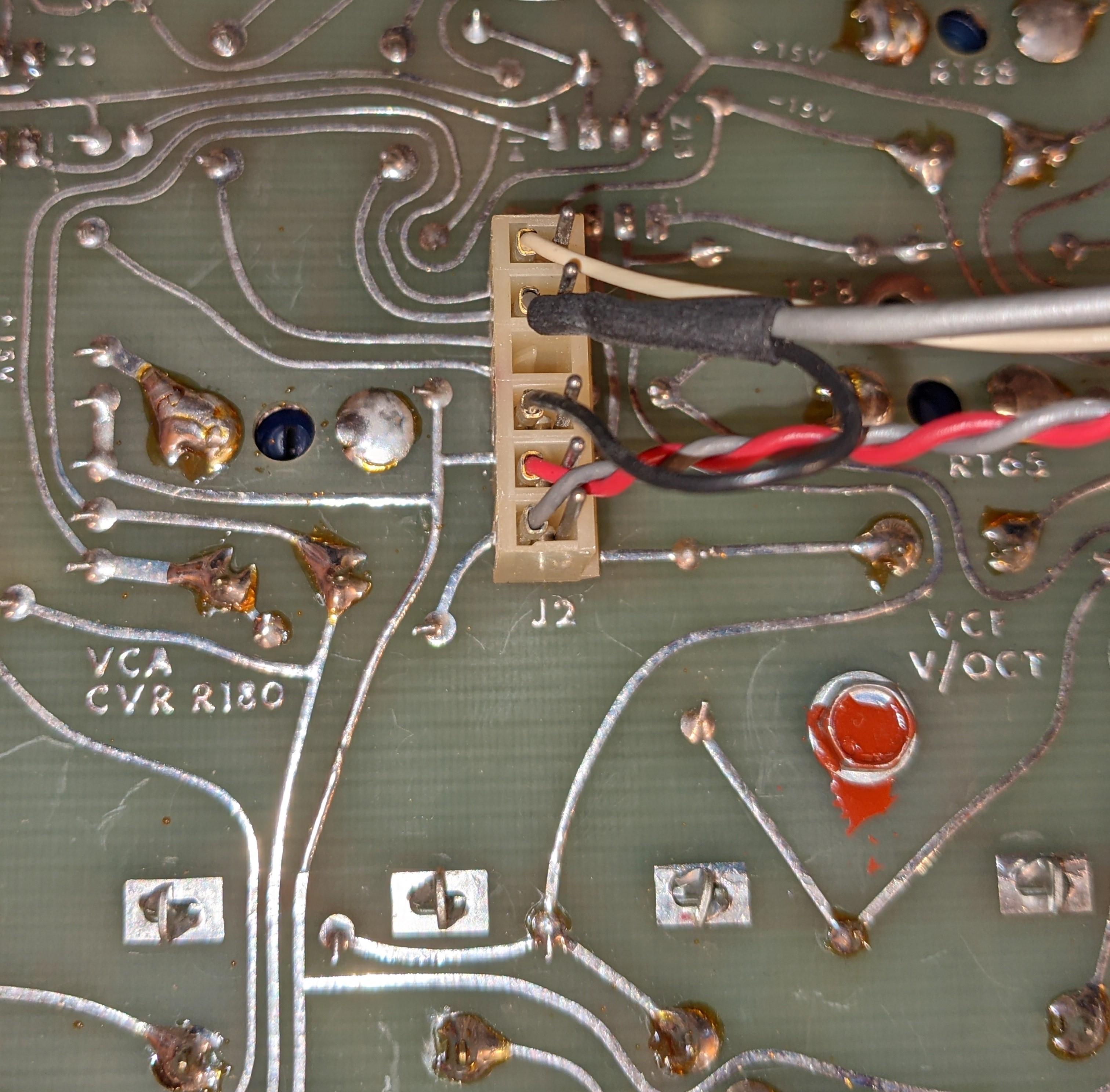
The signal leaves the oscillator board, goes through the mode (waveform) selector switch, and enters the filter board at pin 7. This short video shows the problem, and also demonstrates using an audio probe to listen to the sound inside the synth at various points. Point 11 (see main schematic) is the Repeat input to the filter board.

Exploring the Filter Board

I now know the problem is on the filter board. As you can see from the block diagram, the filters are sequential: high-pass then low-pass and into a VCA made of discrete components.

Filter Circuit Board

I believe the VCA is fine. The envelope generator controls (Sustain, Attack, Percussion, Singing) all cause the expected volume changes. When you turn on Expand, the envelope is applied to both filters, and that works, too. The sound from the VCA also responds to moving the traveler knobs (the filter controls).

The low-pass filter “IC” has already been replaced. The high-pass is original. There are other components on the board, though, for controlling the filter, so the problem may not be in a filter IC.

Filter circuit

The filter chips are the SAME, they are just set up differently. There are some resistor changes and the input is changed! Instead of pin 5, it is pin 4.

Pin 1 is the CV input from the associated traveler. Pin 6 is feedback. Pin 5 is the audio signal input. Pin 8 is the filter output. There is an unlabeled test point in the upper left corner of the filter board- this is the output signal on its way to the VCA circuitry. This should be enough information for me to listen in at those points and see where the audio is changing from my nice input to a single pitch no matter the key press.

The main output from the filter board is at point 23. Point 4 is the Expand input from the envelope generator.

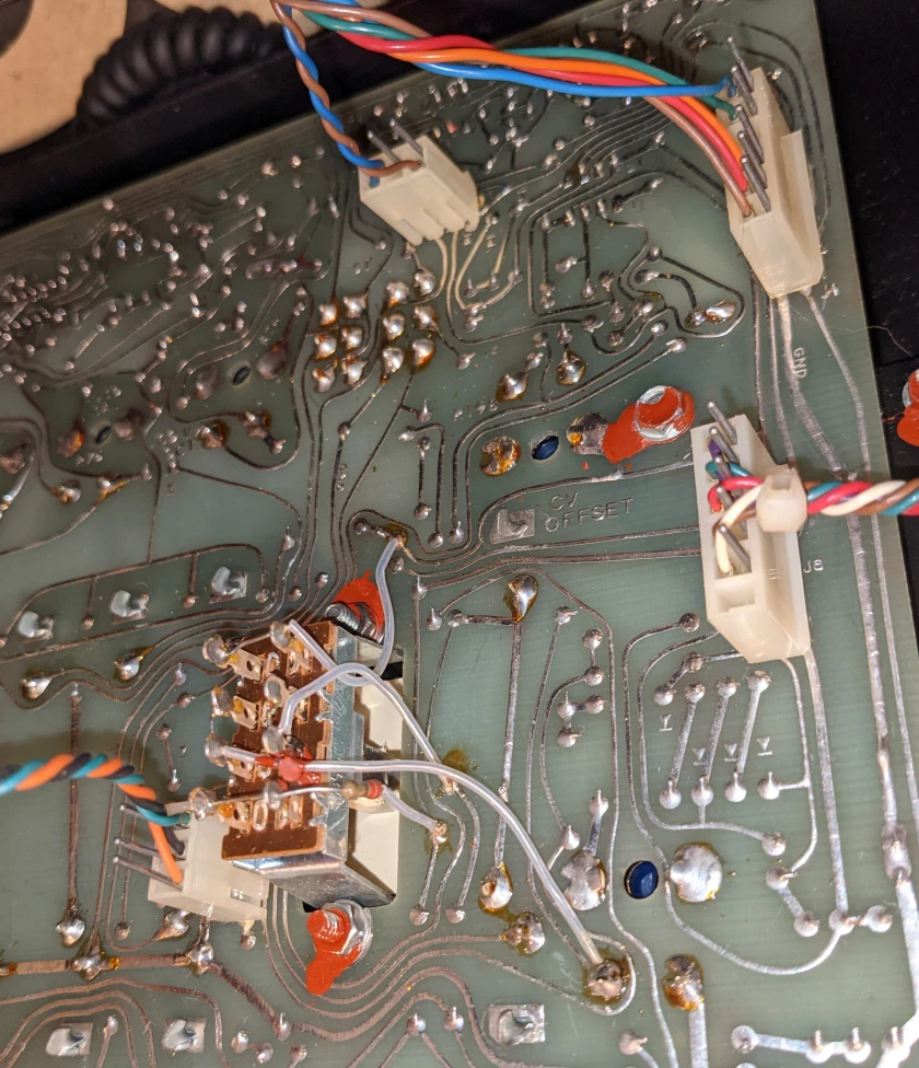
There is one more thing that bothers me- the role of point 53. It is connected to scale selection and you can see it in the filter diagram. I think it may be a bias for key tracking. Change the footage, change the bias to the filter. I tested this and found the voltage changes with different footage from 18 to 20v. So this is working.

I lifted the filter board so I could test the readings in and out of the ICs. The input and output of the high-pass filter are good. You can also filter the signal using the traveler as expected. The inputs are hard to find, but pin 2 does has a signal that varies in pitch with key presses. Pin 6 has no real pitch control but responds to filtering. Pin 4 is like pin 6, but not as loud. Nothing from pin 8. I have a hunch that the schematic is wrong. I think 6 is the output, 4 is the feedback, and 2 the input on the low pass filter. I decided to crank up my amp and give a closer listen. The main output DOES vary with key presses, but only when the LPF is closed, and you just get a DTMF type sound. The dominant signal, which does not change with key presses, becomes stronger as you open the filter.

This post got really long, so you will have to read Part Two for the remaining electronic repairs.

Key Repair and Key Cleaning

One key was broken during shipping. I was able to splint it and glue the broken piece bad on. I keep odd bits of plastic, wood, and metal around for jobs like this. I have found that vintage synths often require some non-electrical work to the case, keys, and circuit boards. A Dremel is also a key tool for making or repairing parts.

I inserted some wood and a bit of sandpaper as a shim to make it fit tight while the glue dried. The little vice is awesome and can move in 3 dimensions!

Holding the key parts and splint while the glue dries

Cleaning is not hard, just a little tedious. I use a car care cleaner designed for plastics. It can also remove craze from metal. A microfiber cloth and a nylon bristle brush handle the cleaning.

**BONUS CONTENT**

More Electrical Safety

Don’t let your body be a path for current flow from the line voltage to ground. Ground in this case can be the metal case, or simply the ground you are standing on.

Why is the fuse on the hot (line current) wire? If the fuse blows, the circuit is de-energized since the hot line current does not pass through the fuse. If the fuse is on the neutral (return) line, then the circuit is still energized even if the fuse is blown, and can shock you. It won’t operate since there is no return path for current, BUT THERE IS LINE VOLTAGE STILL AT THE SWITCH AND TRANSFORMER (if you turned it on). IF YOU TOUCH THEM WHILE GROUNDED YOU BECOME THE PATH FOR CURRENT FLOW.

If a fuse keeps blowing, don’t keep replacing it. Figure out the cause and fix it.

Building a Replacement Frequency Divider

If you need a new MN131 or MN133, the parts are rare and expensive. https://shop.smelektronik.ch/pi/en/IC-out-of-production/IC-for-Musicinstruments1/IC-Music-Keyboards-Organs1/ic-music-mn131a.html

A frequency divider is a common circuit. Problem is knowing the specs, like output voltage range. Some smart guys may have figured it out. The following is from https://sub-continental.com/diy_eng.html#minikorg

MN133 and MN131A are very rare and obsolete frequency divider integrated circuits, they are very difficult to find or at an insane price. Here’s a little substitution circuit that will allow you to make your MiniKorg 700S synth octave divider work again with a CD4024BE IC and few transistors. You will have to unsolder and remove the MN133 (or MN131A) from the board, to remove the two 33K resistors (crossed out in red on the schematic) and to wire the circuit as indicated. The 2K trimmer for the LM317LZ adjustment will allow you to trim the right sawtooth waveform for all the octaves.
One last important thing is that you need to use a shielded wire for the signal that is drawn in purple in the schematic.

Some tips on this diagram. 7’s have slashes through them (European style). 1’s almost look like an upside down ‘V’. The Vreg points all come together to a single joint; this is how the circuit and CD4024 is powered from the LM317. The voltage input to the LM317 is the 20V positive rail of the synth.

ARP Axxe Mark II Repair

Overall, the synth is in pretty good shape. Just doesn’t make a sound. My favorite kind of synth to buy- broken!

After repairing the synth electronics and rebuilding the keybed and broken keys (see https://erichizdepski.wordpress.com/2021/08/01/arp-axxe-keyboard-repair/ ) this synth sounds great. Read below for details of the repair.

Tantalum Capacitors

I have been reading and asking questions about these. Consensus is replace with new tantalums if the old ones are bad. While you can replace with electrolytic capacitors (low ESR, too, maybe), they are not as long-lasting and may have side effects- not passing AC noise to ground as well, for example. If you use ceramics (any non-polarized capacitor) for decoupling/bypass in a dual voltage system, you will short the positive and negative rails together!!

Shorts on PSU Board

Blown fuse. The fuse is soldered to the board so I will put in a fuse holder. It is a 1/8 amp, 250v slow blow fuse.Anticipate a capacitor shorted to ground that also shorted out two diodes in the full-wave rectifier bridge when it went bad. Maybe more damage but those three shorted components are pretty certain.

I also replaced some of the hardware holding the board in place. The old hex screws made it really hard to remove for work so longer screws with nuts have been installed. One standoff was damaged and replaced, too.

The PSU puts out +/- 15 volts (14.8 as read) and I used it to power a little lightbulb on each rail, which it does. The first time I hooked it back to the main board, magic smoke came out of a capacitor and the fuse blew. I will replace the caps later, but in the meantime it works enough for testing.

The PSU has overcurrent protection built-in courtesy of a 723. That is apparently not working right (smoke and blown fuse!). I replaced the 723 IC, the Tantalum and main filter capacitors on the PSU.

Axxe Dual Voltage Power supply

Shorts on the Main PCB

I am suspecting tantalum caps as the problem here. One power rail is shorted to ground. Other has low resistance (6K?) but may be alright. Where the power connects to the board there are tantalum caps that go to ground. One is bad, I believe, causing a short. I suspect there are more problems but this will be like peeling an onion UNLESS I just replace all the tantalums.

A transistor array (3086) is bad, too, I think. One transistor appears bad but I have to remove it to know for sure.

I did a lot more testing. The 3086 transistor arrays are good. Now they are in sockets. I have not found any more shorts and have checked across every capacitor, resistor, diode.

LM301 op amps are used in the ADSR envelope circuitry. These can be replaced if needed with a NE5534.

Sliders Galore

Sliders vice pots on ARP synths. Really filthy. All but one are giving realistic readings, though that does not mean they work well. I intend to replace any that are no good and clean and lube the others.

There are 23 sliders in all. Here are the basic specs.

  • 100k audio taper – 11
  • 100k linear taper – 6
  • 1M audio taper – 6

Axxe re-assembly

It is very important to plug the cables back into the main board properly. I once sold a Moog Satellite I gave up on because a cable was inserted wrong- it was that close to playing! Similar problem with LED’s on the JX-8P due to a cable being inserted wrong (but I caught that one and it is great now). To save you from that misery, here are the photos for the Axxe. Let the colors and the component labeling be your guide.

Shorts fixed, PSU repaired- here we go!

On to the next test- put it all back together and see what happens! I am just hoping for basic noise at this point. I did many more checks of suspect components and all capacitors that go to ground. Found nothing but that does not mean all the IC’s work. Need power!!

It works!!

The ARP works better than expected

Identifying Other Problems

Once you can hear a synth playing, you can diagnose most of the other problems and get close to which major block(s) have a problem. Once you know the blocks to investigate, studying the schematics and hooking up the o-scope are the next steps. I seem to have a Sample and Hold problem, and the ADSR Envelope signal is not doing anything to the VCF or the VCA, but it DOES affect the VCO (ADSR affects the pitch). I also need to ensure I understand how this synth works, so the studying the user manual is a must.

I have studied the Axxe and its behavior. Here is the list of things to explore and fix.

  • No VCA response to the ADSR envelope
  • No VCF response to the ADSR envelope
  • No PWM response to the ADSR envelope
  • sample & hold has no effect on the VCO (but does affect filter)
  • the LFO does not produce a square wave
  • no key repeat in either mode
  • square wave at 50% PW (slider down) sounds identical to the Saw. Sound does thin out as PW is lowered as expected

Additional Things

  • replace power LED
  • replace PSU filter caps with proper uf high quality capacitors
  • not in tune
  • check power supply voltage output and look at ripple

Detailed Repair Video

The descriptions of the work in the video follow.

Troubleshooting Lessons

When troubleshooting, you need a hypothesis you can test. It has to be based on some reasonable understanding of the circuit in question, else you will be wasting your time trying out things that could not be the cause of your troubles. You can also test along a signal chain through the circuit and verify it looks like it should, or not, as you progress. Which you choose depends on how well you know the circuit.

Lesson One. The block diagram shows two connections between the gate generator and the ADSR, but there are really three per the schematic. Always refer to the schematic. Since I have no ADSR envelopes, maybe the gate signal is bad? Would this make sense? TP3 shown below has a good gate signal. The keyboard plays so the gate signal coming in is good. Combining this information, it is obvious that all 3 signals leaving the gate generator are good so time to look elsewhere.

The next block in the signal chain is the ADSR. It is organized in two halves (the first half is shown below) and all signals go through a chokepoint- IC Z5. This chip is a quad NAND (‘not and’) gate and specifically a CD4011. 4000’s series chips are prone to failure with age. It will be simple to check the output (pin 4) and see if it varies as keys are pressed or not. Then, check the inputs. Turns out pin 4 signal was GOOD. This IC is a quad gate, though, and the other gates in it are used elsewhere in the ADSR circuit, so more testing is needed. In addition to the test points, the manual has another ten graphs that show the inner functioning of the ADSR circuit and where to test. Most are on this single 4011, but there are some specific transistors that are part of the release circuit, so I need to check their readings against the graphs. Compounding this, the release slider readings also jump all over.

While checking the test points again (4 and 5 for the ADSR), I saw that they were working after all- just a slow change because attack was always on max. I think I missed this before due to poor settings of the sliders. The manual suggested 1/4 up, but I found it simpler to read on the o-scope when set around 3/4.

Why was attack slow? The slider always read the same high value. Installing a jumper (shorting across the slider) created a fast attack and allowed me to verify a few more things worked right. The synth has a long attack, so this one problem was making it seem like the ADSR envelope was not being applied to the VCA or the Filter, but it was. This also explained another phenomenon- the ADSR did apply a signal to the VCO pitch (easy to hear that changing)- so I knew it worked (sort of). With the short attack I could hear the ADSR effect on the VCF more easily. I could also hear it affect the VCA, but I had hoped it would be more dramatic. In any case, it worked. Using the jumper allowed much more testing.

Gate Generator and first half of ADSR

Lesson Two. Now to investigate the release problem. I need to go thoroughly into the additional test points mentioned before, especially the transistors. I have good ADSR envelopes, so where to next? I continued through the manual and took additional readings on the ADSR circuitry but everything was good.

I moved down the signal chain to the VCA and ran into slider problems again. In fact, the VCA Gain (volume slider) does virtually nothing. If set above 1/4, the notes NEVER release because the slider is faulty and gives a signal to the VCA to keep it always on max. (The VCO/VCF are always putting out an audio signal- it is up to the VCA to control whether you hear it or not.) I also found the sustain slider can also cause the notes to not release. It works ok until you reach the bottom of the travel then the last note turns on again. There is a note in the manual about how sustain can affect release. I also replaced a 45-year-old 3086 transistor array while in the synth.

Lesson Three. I know from testing that my LFO square wave signal is good, but it is not affecting the VCO. Sliders go bad with age, so my hypothesis is that I have an open circuit at R78. I can test the resistance across it from CR15 to R85 to check my hypothesis.

R78 readings jump all over the place. The LFO signal is at the input side but not the output. To test this more thoroughly, I soldered in a temporary 100k potentiometer in parallel with R78. This worked great and I could hear the pitch jump up and down, and the amount varied with the pot setting as expected. R78 will be to be worked on or replaced.

LFO Input to the VCO

While looking at the LFO I also tested the auto repeat/key repeat functions again. The LFO signal is present at the switch, so why don’t I hear it pulsing? Part has to do with the sustain setting. If set high, it makes it hard to hear the pulse. The rest had to do with the long attack masking the presence of the pulses. Once I jumpered across the attack slider, I could hear the pulses and they worked fine in auto repeat and key repeat modes.

I also have a S/H problem, so will look at R77. It affects the VCF but not the VCO. I approached this problem the same as the others and put a 100k pot in parallel with the suspect slider. This caused the pitch to start changing as desired and proved that circuit all worked, it was just a bad slider (again).

Results

Other than the PSU problems (I think the IC 723 failure is what caused things to fail), every other problem with this synth is due to a bad/dirty slider. Until you sort those out, you can’t test the rest properly. My simple technique is to either jumper across the slider (setting it to 0 ohms) or put a pot in parallel with it so I have some control. This makes it easy to get into checking/calibrating everything else since you can get back to the sliders later.

Here is the original work list and current status.

  • No VCA response to the ADSR envelope – bad attack, sustain and VCA gain slider
  • No VCF response to the ADSR envelope – it is there, but hid by slow attack
  • No PWM response to the ADSR envelope – hid by slow attack
  • sample & hold has no effect on the VCO (but does affect filter) – bad S/H slider
  • the LFO does not produce a square wave – bad LFO amount to VCO slider
  • no key repeat in either mode – works fine, long attack and no release was hiding it
  • square wave at 50% PW (slider down) sounds identical to the Saw. Sound does thin out as PW is lowered as expected – works fine, confirmed with scope that waveforms are all good
  • replace power LED – new green LED with a 2.2KOhm series resistor installed
  • replace PSU filter caps with proper uf high quality capacitors – new sprague caps installed
  • not in tune – calibrated and sounds great
  • check power supply voltage output and look at ripple – calibrated and voltage is spot on and clean

Back to the Sliders

I decided to clean these. On the plastic bodies I used a car interior cleaner like Armor All. I used isopropyl and Fader Lube/cleaner (deoxit brand) on the insides. I cleaned them in place so I simply dripped the cleaner into them, worked the sliders, and then used compressed air to help blow out junk and to dry. I slid shop towels (like a thick paper towel) into the slider slots to clean out the inside and that removed the gunk that the IPA Deoxit loosened. I also cleaned the three switches. They worked fine but when you have a synth open, clean everything.

The results? Really impressive. The Square Wave LFO and S/H to the VCO now work!! I removed the jumper shorting the attack slider and after cleaning, it works, too. Sustain and VCA gain sliders work, too, with caveats described below.

The only remaining issues are if sustain is all the way down the signal jumps back up as if set to full sustain and notes don’t release. My sliders do not move super smooth moving, but I have some fader lube (the good grease, not the spray) to fix that.

I thought the VCA Gain slider was odd since you can hear a point just below 1/4 where the VCA turns off and notes release as they should. Above that point they don’t release, but this also depends on other settings such as how much of the ADSR envelope is applied to the VCA. This is performing as designed. The Axxe and Odyssey VCA lets signal pass through by design.

I can live with this and the synth sounds really great. If you can’t, a new slider kit from Synthchaser.com you install yourself is about $180.

Calibration

The service manual is great and easy to find online. The main board is well-labeled, including all test points. The waveforms for what to see on an o-scope at each test point are in the manual. These are important for determining proper operation (but I rely ever more on what sounds best to my ears). They also will show you what may need fixing during calibration.

The ARP Axxe was the simplest to calibrate and tune of any synth I have worked on. One trick I should mention is that I use a chromatic tuner ( Korg CA-1) whenever a calibration procedure calls for using a frequency counter or o-scope. This makes it simpler and besides, you want to hear what it sounds like and not really on your scope being accurate.

The procedures are also in the manual and here are some useful additional pictures and explanations:

https://syntaur.com/DIYdocs/DIY0022.html

There are many resources on the Axxe.

ARP Axxe Patch Sheet

https://modwiggler.com/forum/viewtopic.php?t=195290

Akai VX90 Troubleshoot and Repair

I have taken a repair job on a VX90. This is the rackmount version of the Akai AX-73, and is a six voice analog synthesizer with digital controls. It uses the CEM 3394 as the voice chip. The symptom on this synth is no audio output, but it does start up and receive MIDI. This tells me that much is working properly and I am hoping to find a single fault that is causing all the trouble.

UPDATE 8 FEB 2021

Did I fix it? YES! Here is living proof. Read below for what the problem was.

One of my new songs

By the way, CEM3394 synths all have a similar architecture. There are quite a few of them so this write up and the videos could help with many other synths from Akai, Doepfer, Sequential and Simmons Drums. See this page: https://en.wikipedia.org/wiki/CEM_and_SSM_chips for more info.

Synth Tour!

I Have The Power

First up, I need to investigate that the power supply is working properly. All synths with digital and analog IC’s have multiple voltages in them for meeting their varied needs. This one has a handful: +/- 15v, +/- 6v, and +/- 5v. There is an analog versions for the 5, 6, and 15 volt pairs. The digital circuitry only needs the digital 5 volt signal. This is for the microprocessors and the LCD. The voltage buses are kept separate and I believe the reason is the analog circuits can handle voltage transients better. Digital circuits just crash.

I tested everything and all the proper voltages are present. One thing to watch for- one of the cables has analog and digital voltages and two grounds- one for analog and one for digital. When testing, making sure you are using the correct ground for the voltage you are checking or you will get funny results.

Side Quests

I tried out some other features of the synth as part of my general troubleshooting and learning process.

MIDI

I change the MIDI channel (the synth is not multi-timbral and uses a global MIDI channel for all 100 patches) and verified that worked fine. For MIDI testing I use an Arturia Microfreak. It is small and fits great on a workbench.

AUTOTUNE

I had an Akai AX-60 so I know Autotune happens so fast you can’t believe it does anything. Not on this synth- it just locks up the system and you have to cycle the power. That is a clue. I had tuning problems on a Mirage (it tunes during boot up) and it was due to the filter chips not getting the signals needed from a DAC. The process would timeout, but still complete booting. This one does NOT timeout. I suspect the voice chips are not getting the signals needed and not responding; hence, timeout.

Cassette Interface

The MIDI implementation does not support saving patches over sysex. Instead, it sends out audio signals that are encoded using FSK. This encoding allows an audio file to store digital data (patch settings). It is just an audio signal, though, which you can record on anything, such as a laptop. You can just hookup to the cassette output, adjust your recording levels to get a good, undistorted signal, and record the patch data. I use Audacity for this and have done it for my AX-60 custom patches, available for free from here:

See and hear tape output (FSK audio) during patch saving

Voices

I next turned my attention to the voice chips and audio signal path in general. If it helps, you can think of a single voice chip as a monophonic modular synth. Works the same way, having a VCO, VCF, VCA and wave form selector in it.

Maybe there was a fault in an audio amp? NO. There is simply no output (pin 19) from any of the voices. Why? There are no input signals.

CEM 3394 in the Akai VX90

If you look upstream of the voice chips you see a bunch of op amps. I don’t expect every op amp to be bad so I ignore them and move to the actual signal router, if you will, from the microprocessor board: the 4051 8-Channel Analog Multiplexer. There are 4 of them and they are responsible for routing the control voltages (CV) from the microprocessors (UPD8255AC) to the correct voice chip CV input at the correct time.

The synth block diagram shows me where to look next and from it I have created a short list of suspects.

  • IC9 (UPD8255AC) is the microprocessor that creates the signal the voice board needs.
  • IC10 (EHK-MD6207) is a DAC and I know I need an analog signal. this converts the signal from IC9 to analog.
  • IC11(LF356N) is also in the signal chain and its output IS THE ANALOG SIGNAL I NEED. Inverter, maybe.
  • The single wire carrying the analog signal.

The block diagram show the signal flow described above.

I tested the microprocessor, IC9, and all 14 data lines are producing a binary signal as expected. I can make it change, too, when changing the MIDI signal or the patch being played. The signals are received at IC10, but it does not produce output. IC11 naturally receives no input.

I still need to verify nothing odd has happened to the DAC power supply, just in case that is the cause. It has unusual voltage requirements as shown below.

CV creation from microprocessor through DAC

I checked power to the DAC and it is good. Chip is cold to the touch, also. Not working at all. Time to find a DAC!

The MD6207 is not easy to find. The manufacturer is Matsushita Panasonic. I asked for help on Facebook and someone found it on the Australian ebay site. I took a look and noticed the chip was actually in New York State. I finally found it on the US ebay site, mixed in with a bunch of ads for – wait for it- brake rotors.

I removed the old DAC, put in an IC socket (28 pin wide- 15mm), and popped in the new chip. Worked like a champ EXCEPT it couldn’t play in tune. Notes were literally out of order on the scale. Then I remembered- the AUTOTUNE button. The synth had not been used for awhile so it needed tuning to fix it up.

While I was in the synth I also replaced the LED in the backlight. To ensure the LED was bright but also would not burn out under about 5v (like the last one, I guess), I put an 80 ohm resistor on the ground return path. This cuts the voltage across the LED by about half.

If you are wondering what the DAC is for, it takes the digital signals from a microprocessor and converts them to analog. The signals are then run through an op amp and into each 4051. These signals are for the control voltages for the CEM 3394 voice chips. They control everything. The switching of the 4051’s has to be perfect to route the analog signal to the correct output at the correct time to make the correct sounds. Simple, huh?

Elka 610

This is probably NOT about a successful repair, since the keyboard I am looking at is in pretty rough shape and would require a major overhaul I beleive to get running. That said, there are still interesting lessons to be learned from looking at this and some mistakes I made.

Initial Inspection of 1972 Elka Rhapsody 610

This keyboard is in rough shape on the inside.

Elka Rhapsody 610

Some fuses were missing or blown, almost all case screws were missing, and the power supply board that converts the transformer AC output to DC was only attached by a single screw. There was also something really odd about how the power switch (which was completely broken and leaking goo down the wiring) was wired in, which lead to me making a mistake when I replaced it.

Each of the 61 keys has its own circuit board that sends off signals when a key is pressed. There are 244 electrolytic caps and most are corroded like above. I tested one and it was not as bad as I expected- low ESR but capacitance a little above tolerance. There are also hundreds of PET (polyester or Mylar film) capacitors with several having obvious cracks. They are not superficial- I moved one and the leg broke out through the side along the crack.

Power Supply

The power supply is pretty advanced being triple voltage. This also requires a special transformer with dual voltage outputs and one being center tapped.

The Center-tap Transformer

Wikipedia has a great article on transformers, including the explanation for how to use a center-tapped one with just two diodes to achieve full-wave rectification of the AC signal. Hint- the inputs are 180 degrees out of phase due to how they are references to ground.

https://en.wikipedia.org/wiki/Rectifier

Transformer Testing

Step one- disconnect the secondary windings from EVERYTHING before testing.

Step two- make sure you are powering the transformer correctly. In my case, a switch was wired wrong because of a mysterious extra wire not in the schematics. This was creating a short circuit before even reaching the transformer and blowing the keyboard main fuse instantly.

A transformer operates based on the ratio of the number of windings between the primary and secondary. The ratio is multiplied by the voltage applied to the primary to find the secondary output.

The transformer tests fine, but the rest of the power supply is bad. Only one of three voltages is present.

As an aside, here is an interesting piece of test gear.

https://www.thegearpage.net/board/index.php?threads/light-bulb-current-limiter-build-thread.1607972/

Power Switch Woes

The power switch -probably not original and definitely not wired as shown in the schematic- cause me trouble, but admittedly I made it worse. Good lessons, though. Soldering on a power switch can over-heat the terminals quickly, melting the plastic around them. I knew this but forgot about 10 minutes ago. I melted a terminal right out of the switch because I forgot to use the click on heat sink shown in the photo. Luckily, I don’t need the third terminal and the switch works fine without it. the other photo is the old switch- all three terminals were wired up even though it is supposed to be just an “on-off” switch. I foolishly wired the new “on-off-on” rocker the same way, initially. This cause one of the “on” positions to create a short circuit in the power lines and blew the fuse before power ever reached the transformer. quite confusing until I did more testing and discovered I had an extra wire that should not be attached. Switch replaced and working fine now.

Now the Real Fun Begins

All of this so far is just the prelude to the real problems. I decided to energize part of the system with a battery rig to provide 27VDC. I did it and was able to see square waves at the Top Octave Generator and some of the frequency divider pins (SAJ110). I already know the boards these chips are on are all likely bad (all PET capacitors had cracks by one lead) but maybe working just a little. The square waves did not last for more than a few minutes and then I discovered there was a short circuit. The good thing is that I know the short is on one of the boards receiving the 27VDC. Here is how I found which one.

Finding which PCB has a short

Note that the board with the short also provides for itself 5v and 15v power through Zener Diodes, and 10v for use by the boards with the frequency divider chips.

Frequency Dividers

There are three boards responsible for producing the 12 notes of an octave for each of the octave ranges of the keyboard. The TOG output feeds the starting frequency to the dividers. It does not directly provide any notes itself, but you can listen to its output by hooking an amp up to it different output pins. Each board provides 4 notes across multiple octaves.

Sn74221 Dual Monostable Multivibrator – the clock pulse generator for the Top Octave Generator chip, AY-1-0212.

Details of the AY-1-0212 Top Octave Generator

The input at pin 2 is the master clock signal that all the outputs are relative to. That is why the tuning potentiometer is connected to the SN74221 at pins 6, 7 and 14, 15 so it can be used to control the clock output frequency from pin 12.

This one has been replaced by a MK50242N. Same pinout and frequency outputs, but pin 9 is not connected internally. It is connected to ground in this circuit so has no effect. It is the voltage difference between pin 1 and 10 that matters.

You can also replace it with a modern FPGA version from Flatkeys in the UK. Great product and price.

Back to the Short Hunt

Craziest problem I have ever had, compounded by components missing from the circuit board and others mysteriously added.

I am slowing narrowing down the location by disconnecting parts and re-testing. Tedious. Make me worry if I have conductive flux, a problem in the board (I doubt that). Might be the one capacitor that joins the circuits together?

Now the circuit is simple: clock makes a pulse and sends it to the TOG. Other than getting power and sharing ground there is really only one connection between the clock and the TOG and I have disconnected it. I will test the clock separately. I also can test the TOG separately if I can get a good clock to it. Pretty high frequency needed.

[a few weeks later, 7 Nov 2020]

I re-created the clock circuit on a breadboard. The old 74221 produces too low a clock HZ signal but I have a new one. I have also replaced everything but resistors on the circuit board. Even some extra resistors added for an unknown reasons were bad. They are not on the schematic along with a mystery trimmer.

PSU Repairs

The PSU does not put out 27 or 20v, the two voltages needed for the keyboard. It only puts out 15v for pedal (though the manual says 9). That is just for a light bulb an optical volume pedal.

I pulled the capacitors and transistors from the board. All were good but two of three power transistors. I replaced all three of those with modern versions that have an integrated heatsink, and now I have a working PSU. Getting a little over 25 volts but that should be fine. The TOG needs a certain differential voltage and I think25 keeps it in spec. I will know soon.

The TOG Board

I am going to re-assembled this board and test with the newly repaired power supply. Better than my battery rig I was using for some testing.

2 Dec 2020 Update

Here is the final lesson on the short circuit hunt. The problem was NOT with the TOG board- it was downstream of it. Removing the TOG board simply cutoff the pathway to the other boards, making it seem like the problem was the TOG board. In fact, it is one or more frequency divider boards. These create the individual notes (4 per board).

I rebuilt the TOG board and the Power Supply. The problem with the power supply was that 2 power transistors were bad, knocking out the +20 and +27v power rails. These are TBC 286 or SGS TIP-29A. TIP-29A is a silicon NPN audio and switching power transistor in a TO-220 case by SGS (now STMicroelectronics).

Elka 610 Power Supply Schematic

Once the PSU was repaired I could properly test the TOG board. What I found was no surprise- the TOG chip was bad. About half the tones sounded OK (though I did not check the frequency of them), but the rest were clearly bad and sounded like multiple tones were being blended in and very dissonant sounding.

TOG (Top Octave Generator) Test with rebuilt PSU

Why did the PSU fail? That gets back to the short circuit hunt. The shorts were naturally causing too much current to go through the power transistors. In fact, I plugged the frequency divider boards back in and broke the power supply again. Other components (ceramic resistor on the TOG board, for one) were getting so hot you could burn yourself on them.

The End

Net result of this work was some good lessons learned on short hunting and rebuilding a circuit board. Given the amount of damage and age of the system, I was never planning to fix it all. I would go crazy replacing hundreds of corroded and cracked capacitors. It is not beyond hope, but is probably not worth it. The parts from this keyboard may allow other 610’s to live a better life!

ARP Quartet Repair – Part Two

So I broke my quartet attempting some circuit bending. Oops. Then it got worse- power supply caps started smoking. I think there was something in the case that slid around and shorted them. Oops again. That’s OK- all fixable. For reference, here is what I did the first time- including ugliness. ARP Quartet Restoration [Restoration is not really accurate]

Why fix a Quartet? Great Strings!

This is a video of me playing the Quartet after the repairs detailed below.

Here We Go!

You need the schematics: Good manual here.

First up, re-test the power supply to make sure I have not damaged it. Disconnect the PSU board A from board F (there is a single 6 wire ribbon cable to pull). Test the power coming out of the 6 pins. The supply is good. I realize this was not tested under load, but fine for a simple check.

20181015_182520.jpg

Second, replace the Board F power supply line filter caps. One started smoking, so just replace all (100 uf 16v). I use solder braid for removing components.

I tested them and found nothing wrong but replaced anyway. I did the replacement and powered up board F and C and left on for a few minutes. No problems so far. Note that boards B, C also have their own filter caps.

One way to evaluate the performance of these capacitors is to look at the ripple voltage with an O-scope. Electrolytic capacitors dry out over time and the symptom is excessive ripple voltage. What this means is the voltage is not steady. When it varies too much it can affect the performance of downstream components that use the voltage.

Third, find what I burned out. I tested all the transistors on boards B and F (diode test of each junction using my volt meter) and all are good. So I have a bad IC somewhere.

20181112_141118.jpgSmoke Test

I completed repairs (hackery) for the broken socket and re-connected all the boards in preparation for powering up. Last time I did this, smoke started coming out from a capacitor, or so I assumed. This time, it smoked again but I found the culprit- NC5532 on Board B cracked and smoked. This was great news- I love finding a problem. I swapped it out and have since ran the board for a few hours with no further trouble. I suspect this IC was damaged during my mod attempts. It was in the sustain and decay path, and I had been feeding signals into the synth from a function generator and then it quit working. The next time I powered on I had smoke. No coincidence here.

Test Points

You need to use these to diagnose the circuit performance and verify if working. There are 25. The schematics are old and hard to read, so I have done the work for you of finding the test points. Below are pictures showing where all the test points are on the schematics. That will help you find them on boards.

I have tested several parts of the synth and it is going pretty well:

  • vibrato works along with rate control for vibrato
  • key up and down presses work (send a gate signal)
  • The LFO and HFO for creating signals to make string sounds work

20181112_112508.jpg
Boards are connected at a right-angle. The pins and sockets easily separate.

Switch, LED and Slider Testing

Simple to check your LEDs light up, as long as you know when they should light up. The switches set up different preset sounds, basically, and the LEDs tell you what is going on.

I also tested the resistance of all the sliders – one is really bad and read 20- 30 mega ohms vice 1 mega ohms. I will put a pot in parallel with it to test what is really going on, once I have some sounds coming out. Since I am a hacker, I merely bypassed the bad slider with a 1M ohm resistor for now. I put a potentiometer in series and tested various settings and found I liked 1M ohm the best for the brass anyway. (I will either really fix or disclose at sale later.)

Uh-Oh – Bad Cables!

Major problem with one board to board jumper. Years ago I removed the socket- my notes say it would not hold all the pins tight enough for a connection. Now a wire broke, leaving its stub in the socket and another broke free from the pcb. Finding where to re-attach the ‘free’ wire was simple- just follow the trace from the solder point I damaged (too much heat lifted the soldering pad- you can see burn marks on PCB on the right side) to a via that runs through the board to the top. This is a double-sided pcb so vias are everywhere.

20181112_112704.jpg
Via on left is what I need to connect to since I damaged original solder pad on right.

As for the broken wire I was very lucky. It was unused so nothing to repair!

Here is a general note on identifying bad ribbon or multi-conductor cables. I turned on a synth I am repairing (ARP Quartet) and the voice indicators lights would not turn on. I started checking the power supply voltages (4 are used, since the synth uses some IC requiring dual-voltage power supplies and some logic signals) but they were good. The board controlling voice selection, however, was showing much lower or even 0 when they should be +/- 12 for instance. The particular connecting cable gets flexed and stressed whenever the synth is opened (case is hinged) so these are failure prone. I pulled the board end of the cable delivering power and tested its pins and found several giving bad readings, thus isolating the problem to the cable. I fully removed it, and 5 of 6 pins broke and stayed in the socket. These were clearly already damaged and giving high resistance resulting in the low voltage, or already broken resulting in no voltage.

Something like this would work as a replacement: https://www.digikey.com/product-detail/en/8124%2f06+100/3M155851-1-ND/8256332/?itemSeq=277413756

I fixed the problem by using breadboard jumper wires. Works perfect.

Missing Waveforms

Now I am trying to track down why I have no waveforms coming from board C and hence no sound. This circuit diagram is very useful- the upper TDA 1008 shows the functional output while the lower one shows pin numbers, useful for correlating to the pinout for the TDA 1008.

The Top Octave Synthesizer generates 12 notes (frequency outputs; square waves I think). Each note is sent to a corresponding TDA 1008 to Pin 15, the input. The TDA 1008 also gets a signal from the keyboard- which key pressed determines the octave of the output note (that is, the final frequency generated). Each TDA 1008 serves all octaves for a single letter note (that is, C2, C3, C4, C5, C6 for IC c 3). Pins 8 – 12 sense key presses for the different octaves. The outputs are pins 2-6.

Screen Shot 2018-11-17 at 10.12.59 PM
Board C Schematic- Note Generation

All relations between outputs in the columns and rows are factors of two; that is, they represent different octaves of the same note.

Screen Shot 2018-11-17 at 10.16.09 PM

Pin 7 is for the sustain signal. All TDA 1008’s get the same signal for sustain. There is a single slide potentiometer that controls the sustain voltage signal. I checked this with a voltmeter and Pin 7 responds to sustain slider changes (the voltage ranges from about 0.8 to 1.6v).

Pins 2-6 put out a square wave, with about 600mV peak to peak. In this application, 12v vice 9v is applied as input to 2-6.

The Master Clock

Board C is remarkably easy to access. There are two screws on the bottom of the synth near the front edge. These hold the frame for the key bed. Take these out and you can simple rotate the whole bed by lifting the front edge of the keys. The bed rotates up to a 90 degree position, exposing Board C underneath. Perfect!

20181117_194930.jpg
The clock chip (4069) is on far right. Second from right is the Top Octave Synthesizer (MK 50242)

My troubleshooting approach was simple. Look at the schematic for the ins and outs of Board C. Check those signals with a voltmeter or O-scope as appropriate. I had vibrato, sustain, and key bus voltage, but no outputs. I worked backwards from the output IC, checking the TDA 1008 chips just to ensure they were powered properly, had sustain. All was good except no input or output. This led me to check the Top Octave Synthesizer – no output. It did have input, but the signal did not look right.

The problem I discovered with the O-scope is that even though the master clock chip (4069; IC c1) was giving good vibrato signals, it was NOT putting out a good master clock signal to the Top Octave Synthesizer (IC c2; MK50242). The signal was not a clean square wave and was rather random. Consequently, the Top Octave Synthesizer was not putting out any note frequencies to the other chips, so they could not put out individual notes wave forms (simple square waves) either. There was no output from Board C (IC c15). Without the square waves at each note’s frequency, Boards F and B cannot do any shaping into the different waveforms for the synth voices.

I replaced the 4069 Master Clock IC and voila! Instant good clock and outputs to all the other chips involving in making the square waves for different notes. I also replaced the 1458 (which acts like a summer) with a 5532. Better chip.

The vibrato is sounding better, now, too. Tuning is perfect across all octaves by the way, and very simple to adjust. There is no range/scale calibration procedure like mono-synths of the era, just a simple potentiometer on the right side of the keyboard. I use a Korg chromatic tuner with a 1/4″ input for synth tuning.

Cleaning the Key Bus

20181117_201112_HDR.jpg
Our sponsor

When I looked at the key bus I noticed it was darkened with tarnish. I cleaned it with deoxit and a soft cloth. I sprayed the cloth, then wrapped it around short segments of the bus and sawed gently back and forth. Be careful not to touch the springs used as the contacts for the keys. They can come out of their holder, but are easy to re-insert. They are also delicate so don’t stretch/damage them!

The problem a dirty bus can cause is note re-trigger. I know this since I had re-trigger before cleaning, and none after. Here is the theory: press a key, make contact, fire the envelope and a note plays. Tarnish causes the circuit to break, though the key is still down, but it then re-connects. A new signal is generated and the note plays a second time. Cleaning the bus prevents these intermittent/poor connections that lead to re-triggering.

Calibration

Boards B and F each have a small trimmer potentiometer. The manual has the adjustment procedure (requires the O-Scope). You can also just use your ears and adjust how you like.

More Tips

One thing I did to help me understand this circuit better is I looked at the pinouts and data sheets for all the IC’s so I could understand their functions. This way, I knew what signals to expect under different conditions (switch and slider positions) and could go far beyond the basic test points in the manual for troubleshooting.

This guy is good and has some tips on the Quartet. One of very few people in the world, I believe. Quartet Notes on SoundDoctorin

Detailed Test Point Locations

The manual has a page showing the waveforms expected at these test points.

board B test points

board C test points

board F part 1 test points

board F part 2 test points

board F part 3 test points

board F part 4 test points