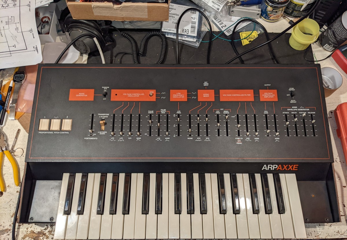
Overall, the synth is in pretty good shape. Just doesn’t make a sound. My favorite kind of synth to buy- broken!
After repairing the synth electronics and rebuilding the keybed and broken keys (see https://erichizdepski.wordpress.com/2021/08/01/arp-axxe-keyboard-repair/ ) this synth sounds great. Read below for details of the repair.
Tantalum Capacitors
I have been reading and asking questions about these. Consensus is replace with new tantalums if the old ones are bad. While you can replace with electrolytic capacitors (low ESR, too, maybe), they are not as long-lasting and may have side effects- not passing AC noise to ground as well, for example. If you use ceramics (any non-polarized capacitor) for decoupling/bypass in a dual voltage system, you will short the positive and negative rails together!!
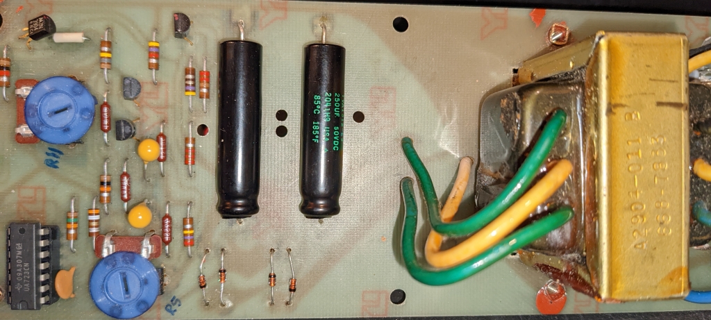
Shorts on PSU Board
Blown fuse. The fuse is soldered to the board so I will put in a fuse holder. It is a 1/8 amp, 250v slow blow fuse.Anticipate a capacitor shorted to ground that also shorted out two diodes in the full-wave rectifier bridge when it went bad. Maybe more damage but those three shorted components are pretty certain.
I also replaced some of the hardware holding the board in place. The old hex screws made it really hard to remove for work so longer screws with nuts have been installed. One standoff was damaged and replaced, too.
The PSU puts out +/- 15 volts (14.8 as read) and I used it to power a little lightbulb on each rail, which it does. The first time I hooked it back to the main board, magic smoke came out of a capacitor and the fuse blew. I will replace the caps later, but in the meantime it works enough for testing.
The PSU has overcurrent protection built-in courtesy of a 723. That is apparently not working right (smoke and blown fuse!). I replaced the 723 IC, the Tantalum and main filter capacitors on the PSU.
Shorts on the Main PCB
I am suspecting tantalum caps as the problem here. One power rail is shorted to ground. Other has low resistance (6K?) but may be alright. Where the power connects to the board there are tantalum caps that go to ground. One is bad, I believe, causing a short. I suspect there are more problems but this will be like peeling an onion UNLESS I just replace all the tantalums.
A transistor array (3086) is bad, too, I think. One transistor appears bad but I have to remove it to know for sure.
I did a lot more testing. The 3086 transistor arrays are good. Now they are in sockets. I have not found any more shorts and have checked across every capacitor, resistor, diode.
LM301 op amps are used in the ADSR envelope circuitry. These can be replaced if needed with a NE5534.
Sliders Galore
Sliders vice pots on ARP synths. Really filthy. All but one are giving realistic readings, though that does not mean they work well. I intend to replace any that are no good and clean and lube the others.
There are 23 sliders in all. Here are the basic specs.
- 100k audio taper – 11
- 100k linear taper – 6
- 1M audio taper – 6
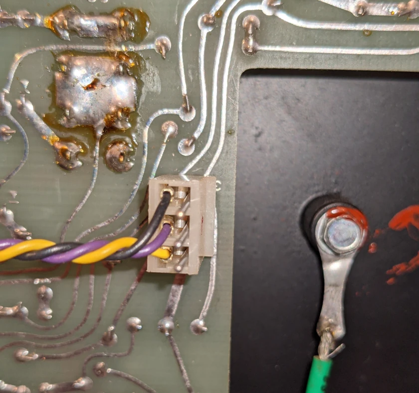
Axxe re-assembly
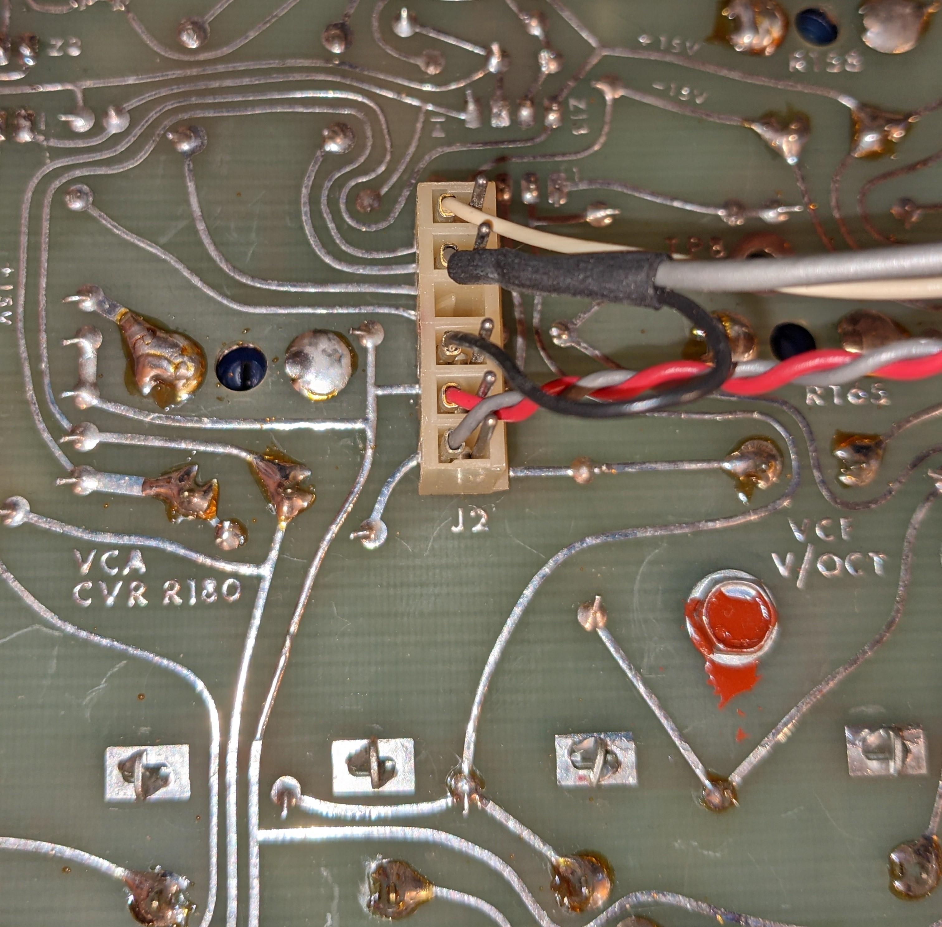
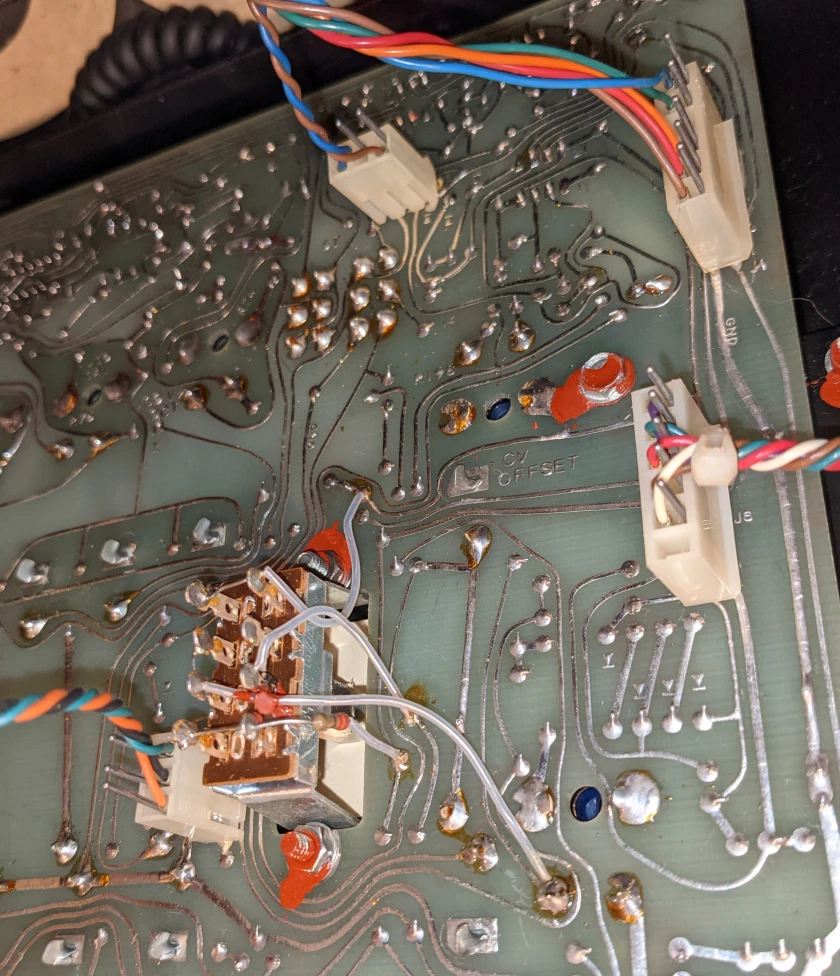
It is very important to plug the cables back into the main board properly. I once sold a Moog Satellite I gave up on because a cable was inserted wrong- it was that close to playing! Similar problem with LED’s on the JX-8P due to a cable being inserted wrong (but I caught that one and it is great now). To save you from that misery, here are the photos for the Axxe. Let the colors and the component labeling be your guide.

Shorts fixed, PSU repaired- here we go!
On to the next test- put it all back together and see what happens! I am just hoping for basic noise at this point. I did many more checks of suspect components and all capacitors that go to ground. Found nothing but that does not mean all the IC’s work. Need power!!
It works!!
Identifying Other Problems
Once you can hear a synth playing, you can diagnose most of the other problems and get close to which major block(s) have a problem. Once you know the blocks to investigate, studying the schematics and hooking up the o-scope are the next steps. I seem to have a Sample and Hold problem, and the ADSR Envelope signal is not doing anything to the VCF or the VCA, but it DOES affect the VCO (ADSR affects the pitch). I also need to ensure I understand how this synth works, so the studying the user manual is a must.
I have studied the Axxe and its behavior. Here is the list of things to explore and fix.
- No VCA response to the ADSR envelope
- No VCF response to the ADSR envelope
- No PWM response to the ADSR envelope
- sample & hold has no effect on the VCO (but does affect filter)
- the LFO does not produce a square wave
- no key repeat in either mode
- square wave at 50% PW (slider down) sounds identical to the Saw. Sound does thin out as PW is lowered as expected
Additional Things
- replace power LED
- replace PSU filter caps with proper uf high quality capacitors
- not in tune
- check power supply voltage output and look at ripple
Detailed Repair Video
The descriptions of the work in the video follow.
Troubleshooting Lessons
When troubleshooting, you need a hypothesis you can test. It has to be based on some reasonable understanding of the circuit in question, else you will be wasting your time trying out things that could not be the cause of your troubles. You can also test along a signal chain through the circuit and verify it looks like it should, or not, as you progress. Which you choose depends on how well you know the circuit.
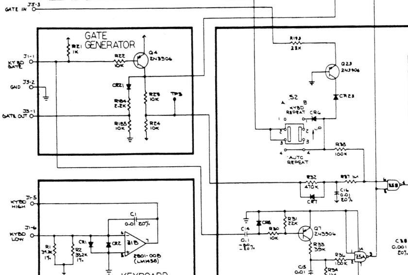
Lesson One. The block diagram shows two connections between the gate generator and the ADSR, but there are really three per the schematic. Always refer to the schematic. Since I have no ADSR envelopes, maybe the gate signal is bad? Would this make sense? TP3 shown below has a good gate signal. The keyboard plays so the gate signal coming in is good. Combining this information, it is obvious that all 3 signals leaving the gate generator are good so time to look elsewhere.
The next block in the signal chain is the ADSR. It is organized in two halves (the first half is shown below) and all signals go through a chokepoint- IC Z5. This chip is a quad NAND (‘not and’) gate and specifically a CD4011. 4000’s series chips are prone to failure with age. It will be simple to check the output (pin 4) and see if it varies as keys are pressed or not. Then, check the inputs. Turns out pin 4 signal was GOOD. This IC is a quad gate, though, and the other gates in it are used elsewhere in the ADSR circuit, so more testing is needed. In addition to the test points, the manual has another ten graphs that show the inner functioning of the ADSR circuit and where to test. Most are on this single 4011, but there are some specific transistors that are part of the release circuit, so I need to check their readings against the graphs. Compounding this, the release slider readings also jump all over.
While checking the test points again (4 and 5 for the ADSR), I saw that they were working after all- just a slow change because attack was always on max. I think I missed this before due to poor settings of the sliders. The manual suggested 1/4 up, but I found it simpler to read on the o-scope when set around 3/4.
Why was attack slow? The slider always read the same high value. Installing a jumper (shorting across the slider) created a fast attack and allowed me to verify a few more things worked right. The synth has a long attack, so this one problem was making it seem like the ADSR envelope was not being applied to the VCA or the Filter, but it was. This also explained another phenomenon- the ADSR did apply a signal to the VCO pitch (easy to hear that changing)- so I knew it worked (sort of). With the short attack I could hear the ADSR effect on the VCF more easily. I could also hear it affect the VCA, but I had hoped it would be more dramatic. In any case, it worked. Using the jumper allowed much more testing.
Lesson Two. Now to investigate the release problem. I need to go thoroughly into the additional test points mentioned before, especially the transistors. I have good ADSR envelopes, so where to next? I continued through the manual and took additional readings on the ADSR circuitry but everything was good.
I moved down the signal chain to the VCA and ran into slider problems again. In fact, the VCA Gain (volume slider) does virtually nothing. If set above 1/4, the notes NEVER release because the slider is faulty and gives a signal to the VCA to keep it always on max. (The VCO/VCF are always putting out an audio signal- it is up to the VCA to control whether you hear it or not.) I also found the sustain slider can also cause the notes to not release. It works ok until you reach the bottom of the travel then the last note turns on again. There is a note in the manual about how sustain can affect release. I also replaced a 45-year-old 3086 transistor array while in the synth.
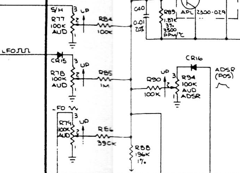
Lesson Three. I know from testing that my LFO square wave signal is good, but it is not affecting the VCO. Sliders go bad with age, so my hypothesis is that I have an open circuit at R78. I can test the resistance across it from CR15 to R85 to check my hypothesis.
R78 readings jump all over the place. The LFO signal is at the input side but not the output. To test this more thoroughly, I soldered in a temporary 100k potentiometer in parallel with R78. This worked great and I could hear the pitch jump up and down, and the amount varied with the pot setting as expected. R78 will be to be worked on or replaced.
While looking at the LFO I also tested the auto repeat/key repeat functions again. The LFO signal is present at the switch, so why don’t I hear it pulsing? Part has to do with the sustain setting. If set high, it makes it hard to hear the pulse. The rest had to do with the long attack masking the presence of the pulses. Once I jumpered across the attack slider, I could hear the pulses and they worked fine in auto repeat and key repeat modes.
I also have a S/H problem, so will look at R77. It affects the VCF but not the VCO. I approached this problem the same as the others and put a 100k pot in parallel with the suspect slider. This caused the pitch to start changing as desired and proved that circuit all worked, it was just a bad slider (again).
Results
Other than the PSU problems (I think the IC 723 failure is what caused things to fail), every other problem with this synth is due to a bad/dirty slider. Until you sort those out, you can’t test the rest properly. My simple technique is to either jumper across the slider (setting it to 0 ohms) or put a pot in parallel with it so I have some control. This makes it easy to get into checking/calibrating everything else since you can get back to the sliders later.
Here is the original work list and current status.
- No VCA response to the ADSR envelope – bad attack, sustain and VCA gain slider
- No VCF response to the ADSR envelope – it is there, but hid by slow attack
- No PWM response to the ADSR envelope – hid by slow attack
- sample & hold has no effect on the VCO (but does affect filter) – bad S/H slider
- the LFO does not produce a square wave – bad LFO amount to VCO slider
- no key repeat in either mode – works fine, long attack and no release was hiding it
- square wave at 50% PW (slider down) sounds identical to the Saw. Sound does thin out as PW is lowered as expected – works fine, confirmed with scope that waveforms are all good
- replace power LED – new green LED with a 2.2KOhm series resistor installed
- replace PSU filter caps with proper uf high quality capacitors – new sprague caps installed
- not in tune – calibrated and sounds great
- check power supply voltage output and look at ripple – calibrated and voltage is spot on and clean
Back to the Sliders
I decided to clean these. On the plastic bodies I used a car interior cleaner like Armor All. I used isopropyl and Fader Lube/cleaner (deoxit brand) on the insides. I cleaned them in place so I simply dripped the cleaner into them, worked the sliders, and then used compressed air to help blow out junk and to dry. I slid shop towels (like a thick paper towel) into the slider slots to clean out the inside and that removed the gunk that the IPA Deoxit loosened. I also cleaned the three switches. They worked fine but when you have a synth open, clean everything.
The results? Really impressive. The Square Wave LFO and S/H to the VCO now work!! I removed the jumper shorting the attack slider and after cleaning, it works, too. Sustain and VCA gain sliders work, too, with caveats described below.
The only remaining issues are if sustain is all the way down the signal jumps back up as if set to full sustain and notes don’t release. My sliders do not move super smooth moving, but I have some fader lube (the good grease, not the spray) to fix that.
I thought the VCA Gain slider was odd since you can hear a point just below 1/4 where the VCA turns off and notes release as they should. Above that point they don’t release, but this also depends on other settings such as how much of the ADSR envelope is applied to the VCA. This is performing as designed. The Axxe and Odyssey VCA lets signal pass through by design.
I can live with this and the synth sounds really great. If you can’t, a new slider kit from Synthchaser.com you install yourself is about $180.
Calibration
The service manual is great and easy to find online. The main board is well-labeled, including all test points. The waveforms for what to see on an o-scope at each test point are in the manual. These are important for determining proper operation (but I rely ever more on what sounds best to my ears). They also will show you what may need fixing during calibration.
The ARP Axxe was the simplest to calibrate and tune of any synth I have worked on. One trick I should mention is that I use a chromatic tuner ( Korg CA-1) whenever a calibration procedure calls for using a frequency counter or o-scope. This makes it simpler and besides, you want to hear what it sounds like and not really on your scope being accurate.
The procedures are also in the manual and here are some useful additional pictures and explanations:
https://syntaur.com/DIYdocs/DIY0022.html
Miscellaneous Links
There are many resources on the Axxe.


