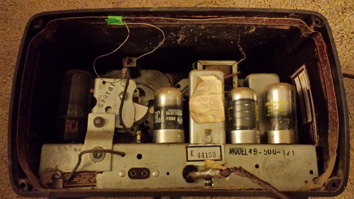
I have a beautiful Philco 49-500 (Walnut brown exterior). At least on the outside. On the inside I have a rotten power cord, a component so burned down it looks like a cigarette butt smoked down to 1/4″, a broken lamp, a lumpy component I call the peanut, resistors with bubbles, and God knows what else. Without much preliminary testing (and a new power cord!) I’m not plugging it in, and even then it will be just to perform testing of circuit portions in isolation until I know things are safe, more or less.
Some write that fixing this kind of radio is not worth the trouble, but I like to do things “not because they are easy, but because they are hard.”
This series is about my thought process on the circuitry and how to test it to ensure maximum safety AND likelihood of success. In the end, I expect to have a working AM radio and quite the room heater!
First, some tips
- Don’t throw out any loose parts- you might need to identify what they are!
- Build a little stand to support the radio chassis so you can flip it over and work on it
- Mark where/how the antenna connects and remove it. It just gets in the way
- Protect your speaker (tape a sheet of cardboard to the metal holder)
I have the schematic for the radio. It’s a free download- just poke around Nostalgia Air. It is not too hard to read, but does require some study and knowledge of electronics, old and new. There are only about 30 components- pretty much just a bunch of resistors, “condensers”- an old term for capacitor, and of course, the TUBES!!
There is a fancy term for this kind of radio- superheterodyne. The common name is All American Five. You should read this wiki entry since it explains designs hazards that could lead to electrical shock. Like don’t plug in and touch the screws on the bottom of radio. Really. And NEVER power up and touch the on/off switch without the cap on it. Yikes. To reduce this risk, I am going to use a polarized plug (original is NOT polarized) and ensure it is wired up correctly. The ‘hot’ wire (from the narrow plug) goes to the rectifier tube, 35Z5 and not the on/off switch. Curious? This page explains it well: Household Wiring
I’m going to do a lot of testing, probably more than I need to do, but that’s OK since I am learning.
Speaker Test
The speaker is of the standard permanent magnet variety. I tested in with a function generator set to produce a TTL square wave. This keeps the voltage/power low to prevent damaging the speaker.
My dial lamp was broken. With the rectifier 35Z5 tube, the lamp should be a #47 (6.3 VDC). The correct voltage is important to proper circuit operation, since it affects the voltage going to the tubes.
Next
There is much more to do so here is a preview.
- I will try to provide a replacement parts list of modern capacitors.
- Replace all wax capacitors, except the tunable ones. One at a time is the best way to go. Replacing the capacitors
- Inspect and clean tube and tube sockets
- Perform resistance checks in the voltage divider circuit that provides all the different DC voltages the radio sub-systems need
- Fire it up (quick smoke test)
Issues
The .04 mf capacitor (part C100) in the power supply section is in two pieces- looks like it burned? If so, why?
The peanut appears to be part T400. Need to test the winding resistance per schematic.
Got parts?
Pieces and parts suppliers and other info
Other Help
More radio repair instructions
